 Sensors
Sensors menu allows to configure any external or internal sensor of Veronte Autopilot 1x.
Accelerometer
Veronte Autopilot 1x incorporates 3 Inertial Measurement Units (IMUs) that allow the 1x system to measure different variables and that are the main navigation data source. In addition, external IMUs can also be used for this purpose.
From the IMU, the user can configure the accelerometer and gyroscope. The first one is explained below.
The user can choose between 3 types of source for the accelerometer:
Internal (Secondary/BMI088/ADIS16505-3 Accelerometer): Autopilot 1x uses the internal sensor.
Warning
If the user has an Autopilot 1x with
hardware version 4.5, the Main Accelerometer is available instead of the ADIS16505-3 Accelerometer, which has the same configurable parameters as the Secondary Accelerometer.External sensor 0-1: Autopilot 1x uses values received from custom messages from a no-integrated external sensor.
Decimal var sensor 0-1: Autopilot 1x uses a decimal value provided by an external sensor.
Hint
Depending on the hardware version, the following accelerometer is suggested:
4.5 versionBMI088 Accelerometer4.8 versionADIS16505-3 Accelerometer
It is possible to select multiple of these sensors for the navigation algorithm, so that Veronte Autopilot 1x performs a combination of all the measurements of the selected accelerometers. This combination consists of calculating the means and variances of each of these accelerometers in a given time (time constant for mean and time constant for variance) to obtain a mean weighted with the inverse of the variance. The lower the variance, the greater the weight of that sensor in the mean.
Common accelerometers configuration
First of all, the parameters to be configured in the accelerometer panel regardless of the selected accelerometer are presented:
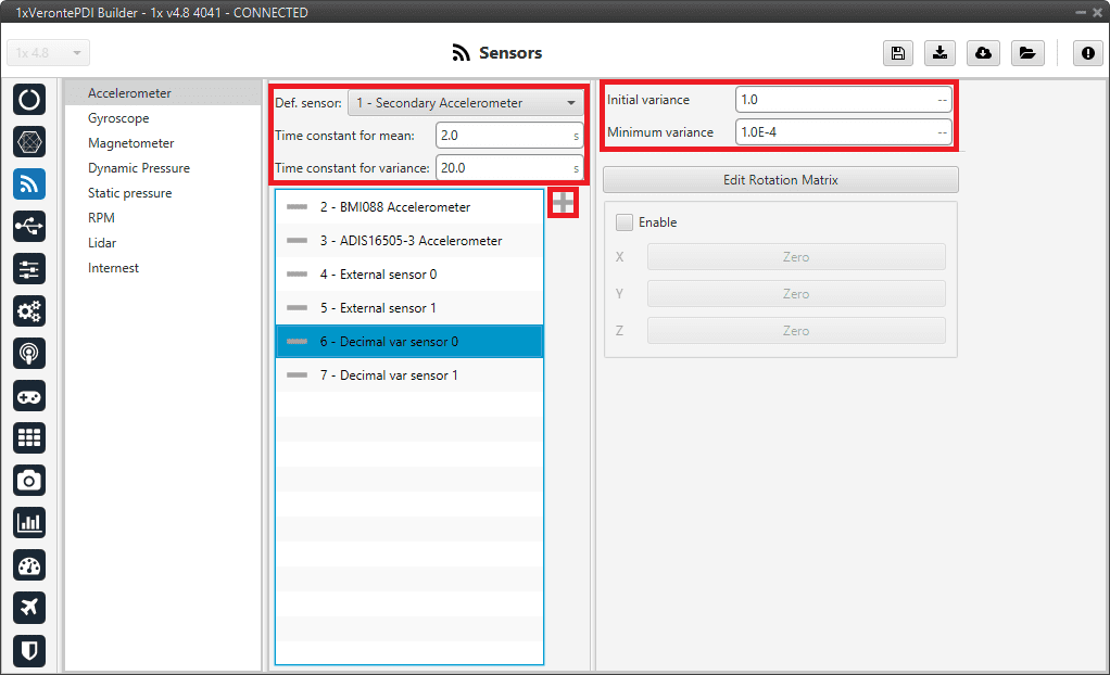
Accelerometer panel
Def. sensor: A default sensor must be chosen. If all selected sensors fail, the measurement value will be that of the default sensor.
Time constant for mean/variance: Time taken by the Autopilot 1x system to estimate the mean/variance.
Initial variance: Initial value of the variance from which the calculation of the combination of the measures is started.
Minimum variance: The value estimated by the system for the variance cannot be less than the one set here.
To select the desired accelerometers, simply add them to the list. To do this, click on the ![]() icon and select them in the panel displayed:
icon and select them in the panel displayed:
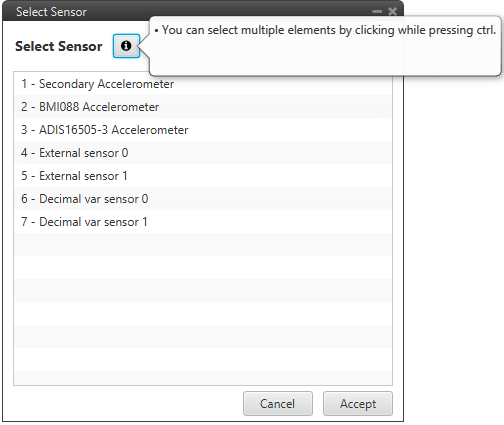
Accelerometer panel - Add accelerometers
Common configuration of the internal accelerometers
Secondly, some configuration parameters that are common to all Internal Accelerometers (Secondary, BMI088 and ADIS16505-3) are explained:
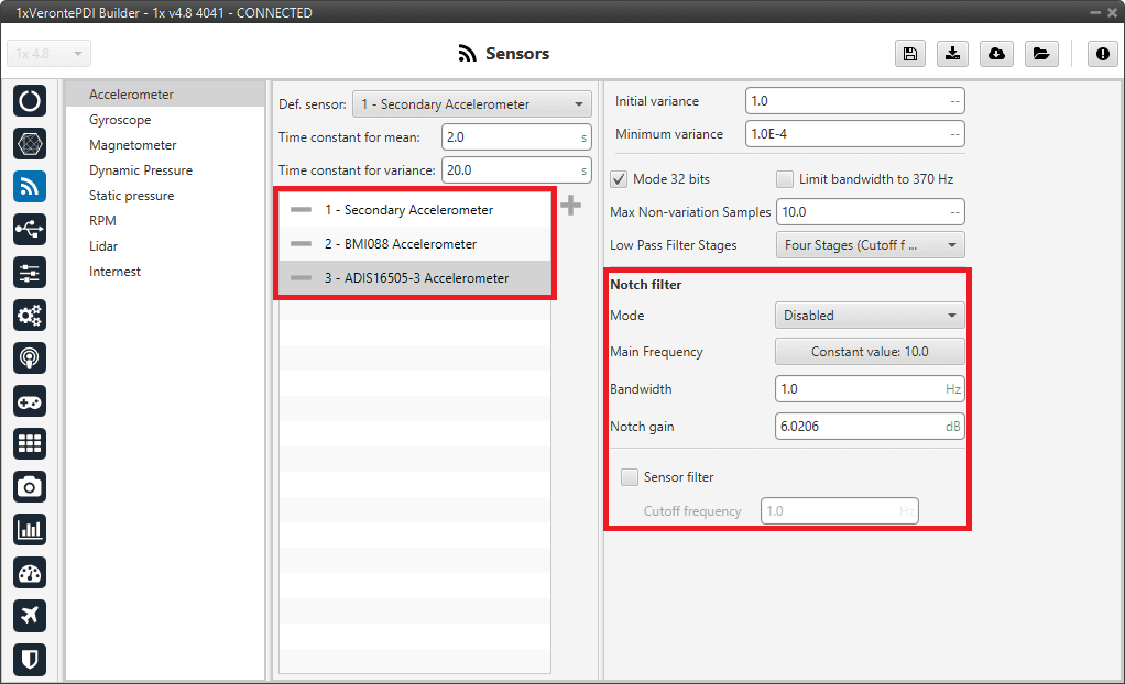
Accelerometer panel - Internal accelerometers configuration
Notch filter: It is a filter that dampens signals only at a specific frequency.
Mode: The available options are:
Disabled: Notch filter disabled.
Main frequency: Only one filter is created on the main frequency.
Main frequency + 1st harmonic: Two filters are created, one at the main frequency and one at the first harmonic, i.e. at the frequency which is twice the main frequency.
Main Frequency: Main frequency (Hz) at which the notch filter reaches its maximum damping.
Bandwidth: Design parameter. There is a damping of at least 3 dB within the bandwidth. The main frequency at which the maximum damping (notch gain) is reached, lies in the center of this spectrum.
Notch gain: Design parameter. This parameters sets the maximum damping (dB) for the main frequency.
Note
Setting this parameter to zero disables the filter.
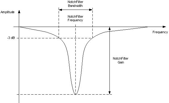
Notch filter
Sensor filter: Enables a low pass filter which its cutoff frequency is configured manually, allowing the user to input any desired value in Hz. It is a software filter.
Sensor
Secondary Accelerometer
This panel displays the possible parameters that can be configured only for the internal Secondary Accelerometer.
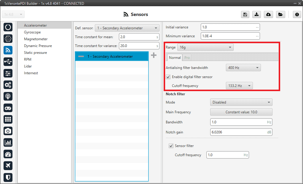
Accelerometer panel - Secondary Accelerometer configuration
In this panel, it is possible to configure different options related to the range and filters of the accelerometer. The parameters that can be modified are:
Note
The configuration parameters common to all accelerometers and also the common to all internal accelerometers, are not explained again.
Range: Selectable range of forces that the accelerometer can measure, high ranges implies less precision while small ranges might mean the system saturates. Values allowed are 2g, 4g, 8g and 16g.
Antialising filter bandwith: It is the bandwidth of the antialiasing low pass filter. The options available are 50Hz, 100Hz, 200Hz and 400Hz, the greater the value selected the worse the filtering will be.
Enable digital filter sensor: Enables a low pass filter which its cutoff frequency is configured from the options 16.65Hz, 66.6Hz, 133.2Hz and 740.0Hz. This is a hardware filter, included directly in the accelerometer.
![]()
BMI088 Accelerometer
This panel displays the possible parameters that can be configured for the internal BMI088 Accelerometer.

Accelerometer panel - BMI088 Accelerometer configuration
In this panel, it is possible to configure different options related to the range and filters of the accelerometer. The parameters that can be modified are:
Note
The configuration parameters common to all accelerometers and also the common to all internal accelerometers, are not explained again.
Range: Selectable range of forces that the accelerometer can measure, high ranges implies less precision while small ranges might mean the system saturates. Values allowed are 3g, 6g, 12g and 24g.
Sampling frequency: That is the frequency at which the measurements are read out. Values allowed are 12.5Hz, 25Hz, 50Hz, 100Hz, 200Hz, 400Hz, 820Hz and 1600Hz. We recommend the highest.
Low pass frequency: This is a hardware filter, included directly in the accelerometer, which its cutoff frequency is configured from the options 145Hz, 234Hz (215Hz for Z axis) and 280Hz (245Hz for Z axis).
![]()
ADIS16505-3 Accelerometer
This panel displays the possible parameters that can be configured for the internal ADIS16505-3 Accelerometer.
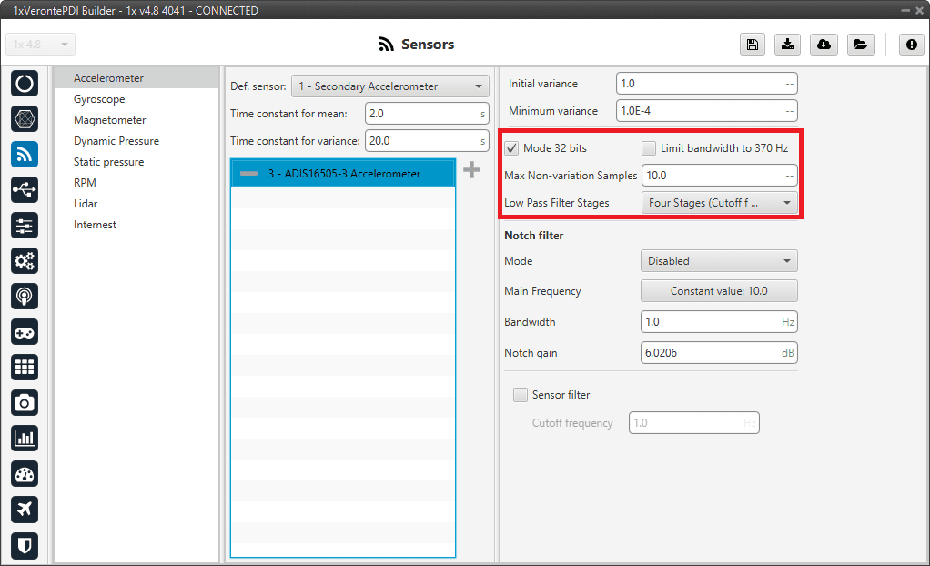
Accelerometer panel - ADIS16505-3 Accelerometer configuration
In this panel it is possible to set different options regarding range and filters from the accelerometer. The parameters that can be modified are:
Note
The configuration parameters common to all accelerometers and also the common to all internal accelerometers, are not explained again.
Mode 32 bits: Enable or disable. With 32 bits of precision. We recommend enabling it.
Limit bandwith to 370Hz: Enable or disable. It can only be used without using a Low Pass Filter Stages. We recommend disabling it.
Max Non-variation Samples: It is configured manually.
Low Pass Filter Stages: IMU’s Hardware filter. The options available are:
No filter
1 stage (Cutoff f=364Hz)
2 stages (Cutoff f=165Hz)
3 stages (Cutoff f=80Hz)
4 stages (Cutoff f=40Hz)
5 stages (Cutoff f=20Hz)
6 stages (Cutoff f=10Hz)
We recommend 4 stages (Cutoff f=40Hz) option.
Warning
It is recommended to choose the hardware filter (Low Pass Filter) except if a lower cutoff frequency is needed (< 10 Hz).
It is not recommended flying without a filter.
![]()
External sensor 0-1
In this panel, the user must configure some parameters in order to correctly receive and manage the measurements from the external sensor.
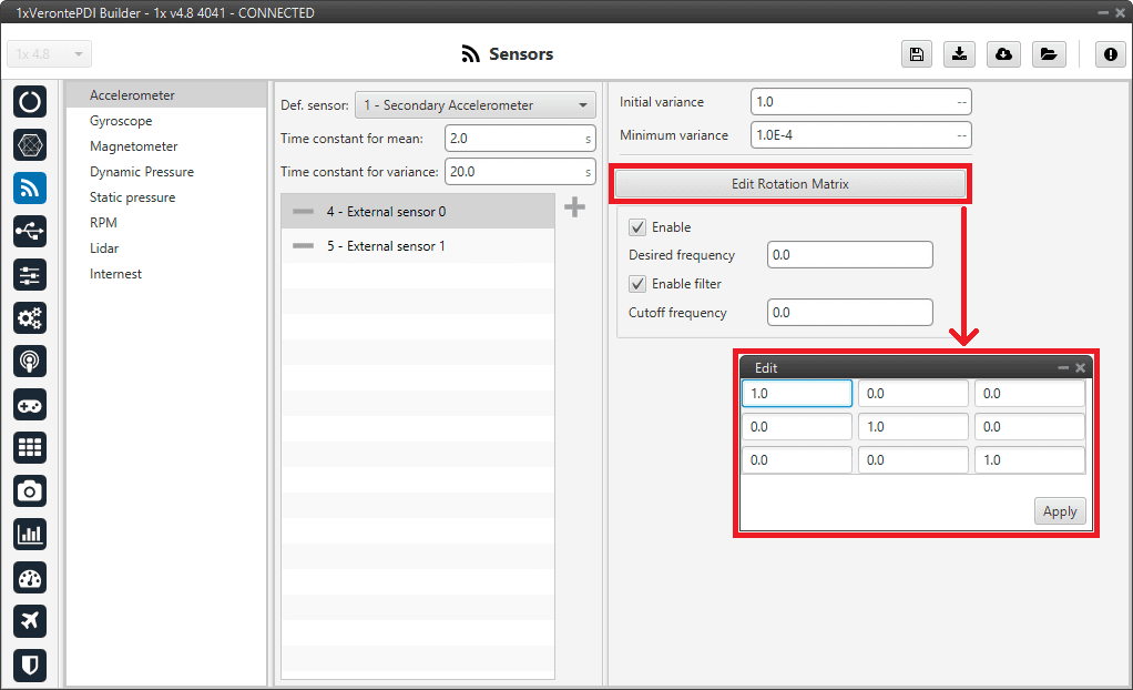
Accelerometer panel - External sensor 0-1 configuration
Note
The configuration parameters common to all accelerometers are not explained again.
Edit Rotation Matrix: Users must set the position of the external sensor with respect to the orientation of the Veronte Autopilot 1x.
Error
The rotation matrix cannot be a zero matrix and must respect the orthogonality of the axes. Not complying with this requirement means an invalid rotation and, consequently, the calibration of this magnetometer will not be possible.
For more information on Autopilot 1x orientation, please refer to the Orientation - Hardware Installation section of the 1x Hardware Manual.
Enable: Users must enable it if they want this sensor to be selected.
Desired frequency: The sensor measurement shall only be considered correct if the frequency at which the message with this measurement is received is \(\geq 90 \%\) of the desired frequency defined here by the user.
This frequency is stored in the RVars 1488-1489. For more information on these variables, see the Real Variables (RVar) - 32 Bits section of the 1x Software Manual.
Enable filter: Enables a butterworth second order low-pass filter which its cutoff frequency is configured manually, allowing the user to input any desired value in Hz.
![]()
Decimal var sensor 0-1
In this panel it is possible to configure real variables provided by an external sensor.
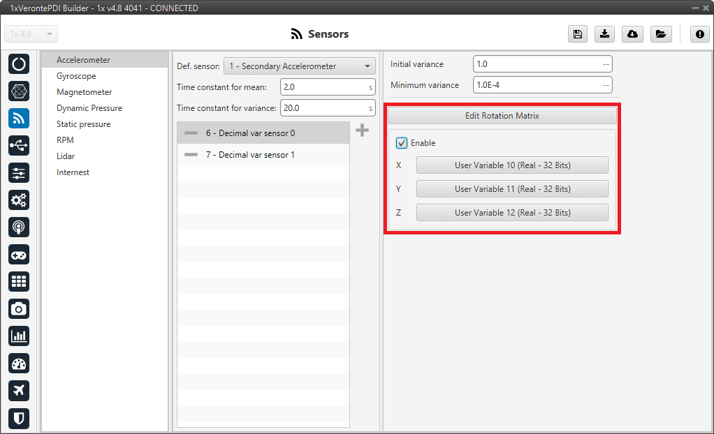
Accelerometer panel - Decimal var sensor 0-1 configuration
Note
The configuration parameters common to all accelerometers are not explained again.
Edit Rotation Matrix: Users must set the position of the external sensor with respect to the orientation of the Veronte Autopilot 1x.
Error
The rotation matrix cannot be a zero matrix and must respect the orthogonality of the axes. Not complying with this requirement means an invalid rotation and, consequently, the calibration of this magnetometer will not be possible.
For more information on Autopilot 1x orientation, please refer to the Orientation - Hardware Installation section of the 1x Hardware Manual.
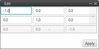
Accelerometer panel - Rotation matrix
Enable: When enabled, the user must select the real user variables for each axis (X,Y,Z) in which the values have been stored.
The configuration process must be done using custom messages. This is to be configured in the Custom Messages panel of the Input/Output menu. The configuration will depend on the device in use and its communication protocol.
Gyroscope
The gyroscope from the IMU can be configured as explained in the panels shown below.
The user can choose between 3 types of source for the gyroscope:
Internal (Secondary/BMI088/ADIS16505-3 Gyroscope): Autopilot 1x uses the internal sensor.
Warning
If the user has an Autopilot 1x with
hardware version 4.5, the Main Gyroscope is available instead of the ADIS16505-3 Gyroscope, which has the same configurable parameters as the Secondary Gyroscope.External sensor 0-1: Autopilot 1x uses values received from custom messages from a no-integrated external sensor.
Decimal var sensor 0-1: Autopilot 1x uses a decimal value provided by an external sensor.
Hint
Depending on the hardware version, the following gyroscope is suggested:
4.5 versionBMI088 Gyroscope4.8 versionADIS16505-3 Gyroscope
It is possible to select multiple of these sensors for the navigation algorithm, so that Veronte Autopilot 1x performs a combination of all the measurements of the selected gyroscopes. This combination consists of calculating the means and variances of each of these gyroscopes in a given time (time constant for mean and time constant for variance) to obtain a mean weighted with the inverse of the variance. The lower the variance, the greater the weight of that sensor in the mean.
Common gyroscopes configuration
First of all, the parameters to be configured in the gyroscope panel regardless of the selected gyroscope are presented:
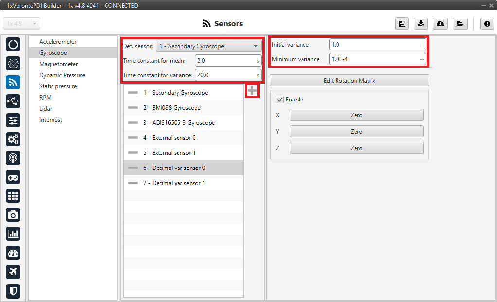
Gyroscope panel
Def. sensor: A default sensor must be chosen. If all selected sensors fail, the measurement value will be that of the default sensor. Default senor must be chosen.
Time constant for mean/variance: Time taken by the Autopilot 1x system to estimate the mean/variance.
Initial variance: Initial value of the variance from which the calculation of the combination of the measures is started.
Minimum variance: The value estimated by the system for the variance cannot be less than the one set here.
To select the desired gyroscopes, simply add them to the list. To do this, click on the ![]() icon and select them in the panel displayed:
icon and select them in the panel displayed:
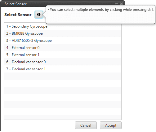
Gyroscope panel - Add gyroscopes
Common configuration of the internal gyroscopes
Secondly, some configuration parameters that are common to all Internal Gyroscopes (Secondary, BMI088 and ADIS16505-3) are explained:
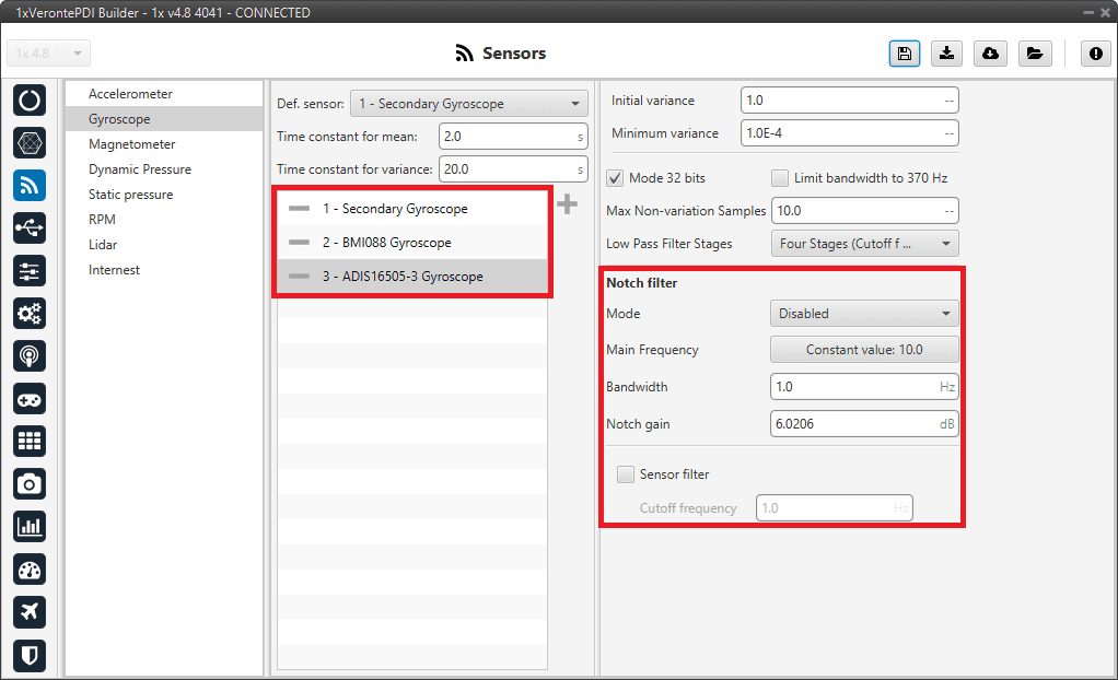
Gyroscope panel - Internal gyroscopes configuration
Notch filter: It is a filter that dampens signals only at a specific frequency.
Mode: The available options are:
Disabled: Notch filter disabled.
Main frequency: Only one filter is created on the main frequency.
Main frequency + 1st harmonic: Two filters are created, one at the main frequency and one at the first harmonic, i.e. at the frequency which is twice the main frequency.
Main Frequency: Main frequency (Hz) at which the notch filter reaches its maximum damping.
Bandwidth: Design parameter. There is a damping of at least 3 dB within the bandwidth. The main frequency at which the maximum damping (notch gain) is reached, lies in the center of this spectrum.
Notch gain: Design parameter. This parameters sets the maximum damping (dB) for the main frequency.
Note
Setting this parameter to zero disables the filter.
Notch filter
Sensor filter: Enables a low pass filter which its cutoff frequency is configured manually, allowing the user to input any desired value in Hz. It is a software filter.
Sensor
Secondary Gyroscope
This panel displays the possible parameters that can be configured for the internal Secondary Gyroscope.
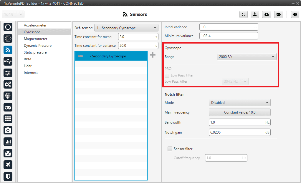
Gyroscope panel - Secondary Gyroscope configuration
In this panel it is possible to set different options regarding range and filters from the gyroscope. The parameters that can be modified are:
Note
The configuration parameters common to all gyroscopes and also the common to all internal gyroscopes, are not explained again.
Range: Sets the maximum range of performance, high ranges implies less precision while small ranges might mean the system saturates. Values allowed are 125°/s, 250°/s, 500°/s, 1000°/s and 2000°/s.
![]()
BMI088 Gyroscope
This panel displays the possible parameters that can be configured for the internal BMI088 Gyroscope.
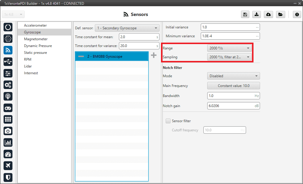
Gyroscope panel - BMI088 Gyroscope configuration
In this panel it is possible to set different options regarding range and filters from the gyroscope. The parameters that can be modified are:
Note
The configuration parameters common to all gyroscopes and also the common to all internal gyroscopes, are not explained again.
Range: Sets the maximum range of performance, high ranges implies less precision while small ranges might mean the system saturates. Values allowed are 125°/s, 250°/s, 500°/s, 1000°/s and 2000°/s.
Sampling: That is the angular velocity at which the measurements are read out. Values allowed are 100°/s filter at 32 Hz, 200°/s filter at 64 Hz, 100°/s filter at 12 Hz, 200°/s filter at 32 Hz, 400°/s filter at 47 Hz, 1000°/s filter at 116 Hz, 2000°/s filter at 230 Hz and 2000°/s filter at 532 Hz.
![]()
ADIS16505-3 Gyroscope
This panel displays the possible parameters that can be configured for the internal ADIS16505-3 Gyroscope.
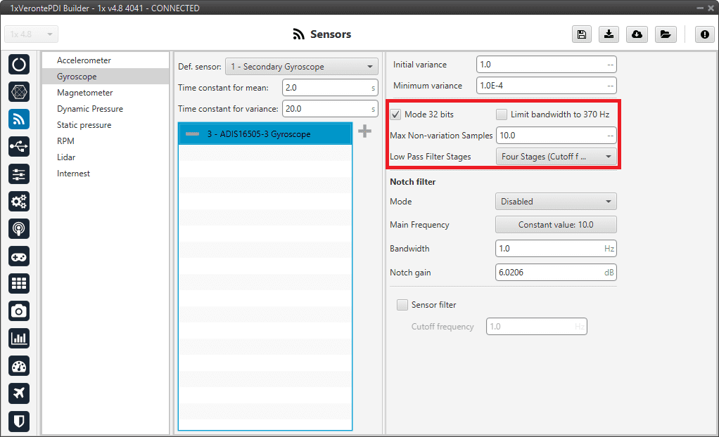
Gyroscope panel - ADIS16505-3 Gyroscope configuration
In this panel it is possible to set different options regarding range and filters from the gyroscope. The parameters that can be modified are:
Note
The configuration parameters common to all gyroscopes and also the common to all internal gyroscopes, are not explained again.
Mode 32 bits: Enable or disable. With 32 bits of precision. We recommend enabling it.
Limit bandwith to 370Hz: Enable or disable. It can only be used without using a Low Pass Filter Stages. We recommend disabling it.
Max Non-variation Samples: It is configured manually.
Low Pass Filter Stages: IMU’s Hardware filter. The options available are:
No filter
1 stage (Cutoff f=364Hz)
2 stages (Cutoff f=165Hz)
3 stages (Cutoff f=80Hz)
4 stages (Cutoff f=40Hz)
5 stages (Cutoff f=20Hz)
6 stages (Cutoff f=10Hz)
We recommend 4 stages (Cutoff f=40Hz) option.
Warning
It is recommended to choose the hardware filter (Low Pass Filter) except if a lower cutoff frequency is needed (< 10 Hz).
It is not recommended flying without a filter.
![]()
External sensor 0-1
In this panel, the user must configure some parameters in order to correctly receive and manage the measurements from the external sensor.
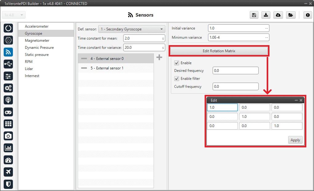
Gyroscope panel - External sensor 0-1 configuration
Note
The configuration parameters common to all gyroscopes are not explained again.
Edit Rotation Matrix: Users must set the position of the external sensor with respect to the orientation of the Veronte Autopilot 1x.
Error
The rotation matrix cannot be a zero matrix and must respect the orthogonality of the axes. Not complying with this requirement means an invalid rotation and, consequently, the calibration of this magnetometer will not be possible.
For more information on Autopilot 1x orientation, please refer to the Orientation - Hardware Installation section of the 1x Hardware Manual.
Enable: Users must enable it if they want this sensor to be selected.
Desired frequency: The sensor measurement shall only be considered correct if the frequency at which the message with this measurement is received is \(\geq 90 \%\) of the desired frequency defined here by the user.
This frequency is stored in the RVars 1488-1489. For more information on these variables, see the Real Variables (RVar) - 32 Bits section of the 1x Software Manual.
Enable filter: Enables a butterworth second order low-pass filter which its cutoff frequency is configured manually, allowing the user to input any desired value in Hz.
![]()
Decimal var sensor 0-1
In this panel it is possible to configure real variables provided by an external sensor.
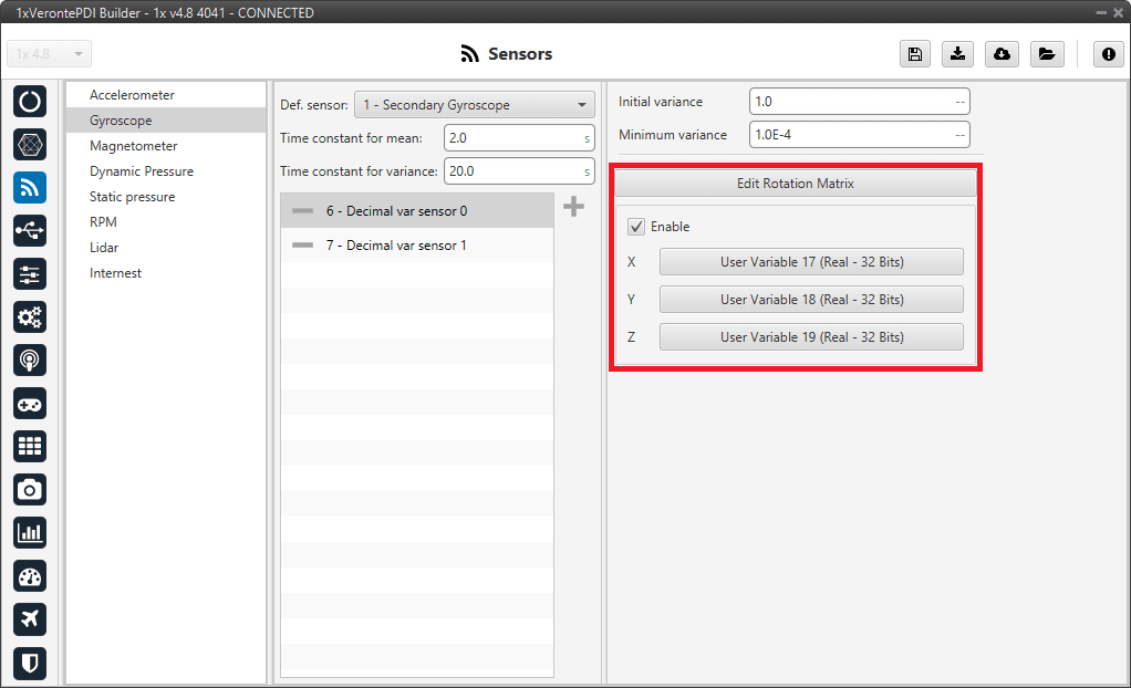
Gyroscope panel - Decimal var sensor 0-1 configuration
Note
The configuration parameters common to all gyroscopes are not explained again.
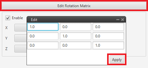
Edit Rotation Matrix: Users must set the position of the external sensor with respect to the orientation of the Veronte Autopilot 1x.
Error
The rotation matrix cannot be a zero matrix and must respect the orthogonality of the axes. Not complying with this requirement means an invalid rotation and, consequently, the calibration of this magnetometer will not be possible.
For more information on Autopilot 1x orientation, please refer to the Orientation - Hardware Installation section of the 1x Hardware Manual.
Gyroscope panel - Rotation matrix
Enable: When enabled, the user must select the real user variables for each axis (X,Y,Z) in which the values have been stored.
The configuration process must be done using custom messages. This is to be configured in the Custom Messages panel of the Input/Output menu. The configuration will depend on the device in use and its communication protocol.
Magnetometer
Veronte Autopilot 1x incorporates three internal magnetometers (only two are available on Autopilots 1x with hardware version 4.5) that allow the 1x system to measure the magnetic field.
In addition, external magnetometers can also be used for this purpose.
The user can choose between 4 types of source for the magnetometer.
Internal (LIS3MDL/MMC5883MA/RM3100): Autopilot 1x uses the internal sensor.
Warning
If the user has an Autopilot 1x with
hardware version 4.5, Internal RM3100 Magnetometer is not available.External sensor 0-1: Autopilot 1x uses values received from custom messages from a no-integrated external sensor.
Decimal var sensor 0-1: Autopilot 1x uses a decimal value provided by a no-integrated external sensor.
External (HMR2300/LIS3MDL/HSCDTD008A/MMC5883MA/RM3100): Autopilot 1x uses the information from one of the compatible external magnetometers.
It is possible to select multiple of these sensors for the navigation algorithm, so the user will have redundancy in magnetometer sensor.
Hint
Depending on the hardware version, the following magnetometer is suggested:
4.5 versionInternal MMC5883MA Magnetometer4.8 versionInternal RM3100 Magnetometer
Note
LIS3MDL and HSCDTD008A Magnetometer are integrated in Autopilot 1x with the I2C interface. They are inside the 1x, but mounted externally to avoid the possible interferences from being close to electronic components.
Magnetometer LIS3MDL: It is a three-axis magnetic sensor with a very small package.
Magnetometer HSCDTD008A: It is a three-axis terrestrial magnetism sensor of the digital output.
It is very important to know that address cannot be chosen in the software and must be as follows:
Magnetometer LIS3MDL: 0x1C.
Magnetometer HSCDTD008A: 0x0C.
Important
In this panel, the user can only modify some configurable parameters, the selection of the magnetometer and the configuration of the Variance are done in the Magnetometer - Sensors blocks of the Block Programs menu.
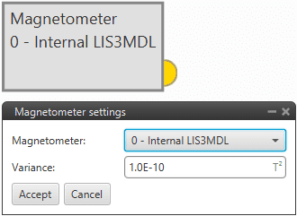
Magnetometer block
Sensor
Internal LIS3MDL/MMC5883MA/RM3100
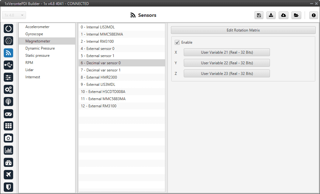
This panel displays the possible parameters that can be configured for the internal magnetometers.
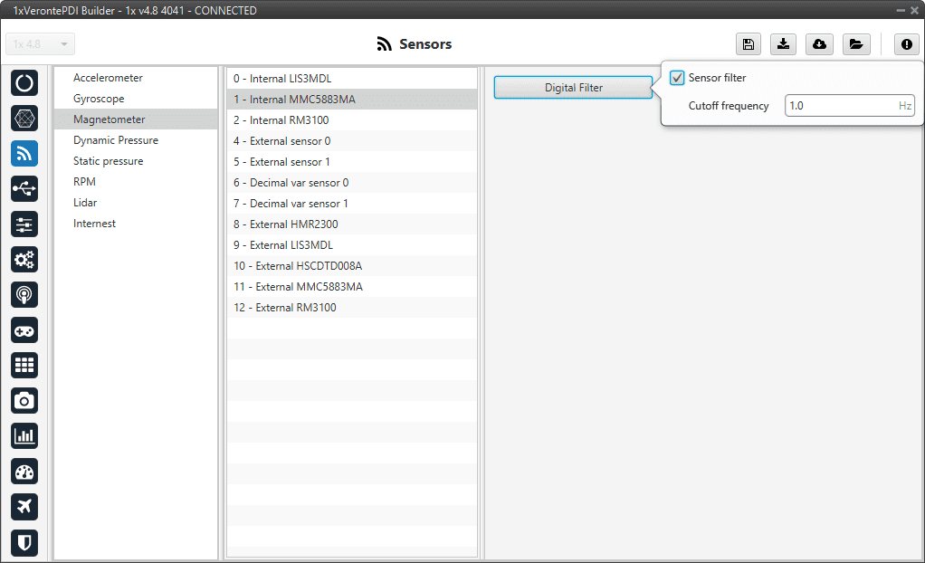
Magnetometer panel - Internal magnetometers configuration
In this panel it is possible the following options regarding the digital filter:
Digital filter: By enabling the Sensor filter checkbox, the user enables a low pass filter which its cutoff frequency is configured manually, allowing the user to input any desired value in Hz. It is a software filter.
![]()
External sensor 0-1
In this panel, the user must configure some parameters in order to correctly receive and manage the measurements from the external sensor.
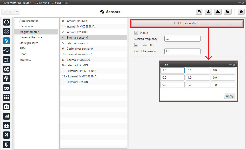
Magnetometer panel - External sensor 0-1 configuration
Edit Rotation Matrix: Users must set the position of the external sensor with respect to the orientation of the Veronte Autopilot 1x.
Error
The rotation matrix cannot be a zero matrix and must respect the orthogonality of the axes. Not complying with this requirement means an invalid rotation and, consequently, the calibration of this magnetometer will not be possible.
For more information on Autopilot 1x orientation, please refer to the Orientation - Hardware Installation section of the 1x Hardware Manual.
Enable: Users must enable it if they want this sensor to be selected.
Desired frequency: The sensor measurement shall only be considered correct if the frequency at which the message with this measurement is received is \(\geq 90 \%\) of the desired frequency defined here by the user.
This frequency is stored in the RVars 1488-1489. For more information on these variables, see the Real Variables (RVar) - 32 Bits section of the 1x Software Manual.
Enable filter: Enables a butterworth second order low-pass filter which its cutoff frequency is configured manually, allowing the user to input any desired value in Hz.
![]()
Decimal var sensor 0-1
In this panel it is possible to configure real variables provided by an external sensor.
Magnetometer panel - Decimal var sensor 0-1 configuration
Edit Rotation Matrix: Users must set the position of the external sensor with respect to the orientation of the Veronte Autopilot 1x.
Error
The rotation matrix cannot be a zero matrix and must respect the orthogonality of the axes. Not complying with this requirement means an invalid rotation and, consequently, the calibration of this magnetometer will not be possible.
For more information on Autopilot 1x orientation, please refer to the Orientation - Hardware Installation section of the 1x Hardware Manual.
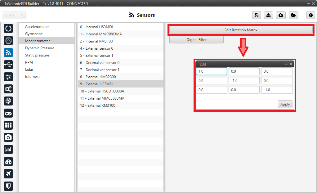
Magentometer panel - Rotation matrix
Enable: When enabled, the user must select the real user variables for each axis (X,Y,Z) in which the values have been stored.
The configuration process must be done using custom messages. This is to be configured in the Custom Messages panel of the Input/Output menu. The configuration will depend on the device in use and its communication protocol.
![]()
External HMR2300/LIS3MDL/HSCDTD008A/MMC5883MA/RM3100
Autopilot 1x has been designed to have compatibility with these external magnetometers.
Magnetometer panel - External magnetometers configuration
The user can modify the following parameters:
Edit Rotation Matrix: It must be modified in the case that the axes of the magnetometer do not coincide with those of the aircraft.
Error
The rotation matrix cannot be a zero matrix and must respect the orthogonality of the axes. Not complying with this requirement means an invalid rotation and, consequently, the calibration of this magnetometer will not be possible.
Digital filter: By enabling the Sensor filter checkbox, the user enables a low pass filter which its cutoff frequency is configured manually, allowing the user to input any desired value in Hz. It is a software filter.
Dynamic Pressure
Autopilot 1x has three pressure input lines, two for static pressure to determine the absolute pressure and one for pitot in order to determine the dynamic pressure.
This panel allows the user to configure a Dynamic Pressure sensor input in 1x.
Navigation
The Navigation panel has 5 parameters that are configured independently from the Dynamic Pressure sensor selected.
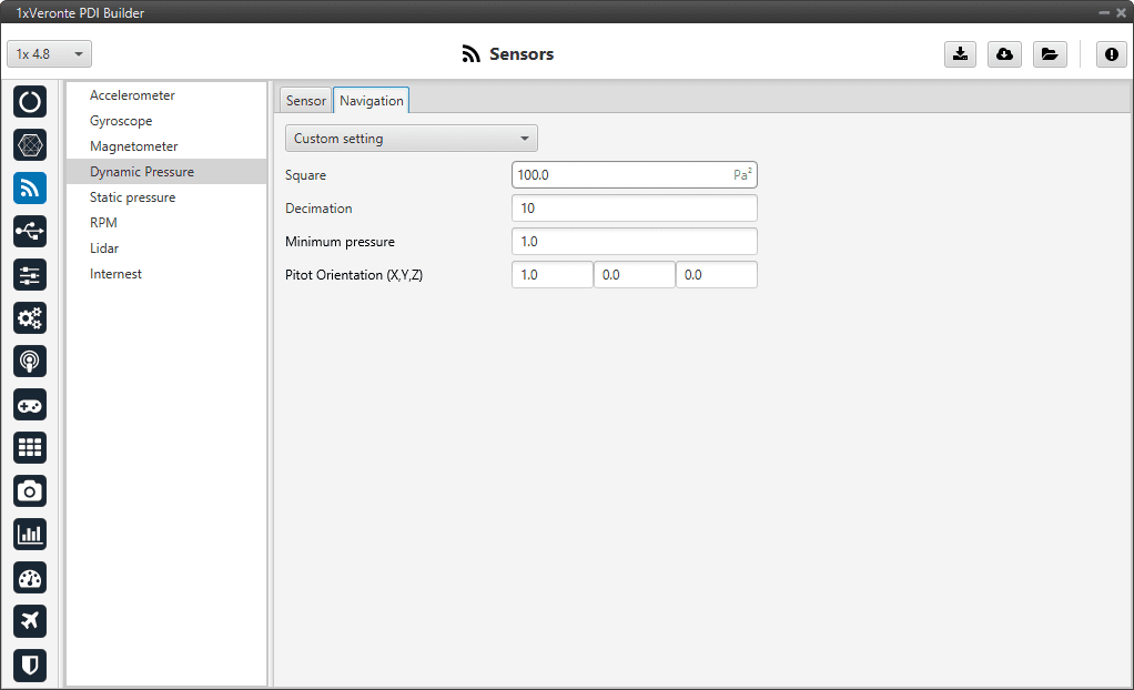
Dynamic Pressure panel - Navigation parameters
Enable: User can choose from Disabled, values from the sensor will be received, but they will not enter the Navigation Filter, or Custom settings, which will take into account all the following parameters.
Square Error: Sensor error square, which defines the weight if the measurement into the Navigation filter.
Decimation: Defines the bunch of data from which 1 value will be stored. For example, if decimation is 10, every 10 measurements 1 will be taken into account. This procedure is used to reduce the number of samples.
If users have any questions about decimation, please refer to the What does decimation mean? - FAQ section of this manual.
Minimum pressure: Minimum pressure readable from the sensor.
Pitot Orientation (X,Y,Z): Vector defining the Pitot orientation on the platform.
Sensor
The user can choose between 3 types of source:
Internal: Autopilot 1x uses the internal sensor.
Integer var sensor 0-1: Autopilot 1x uses a integer value provided by an external sensor.
Decimal var sensor 0-1: Autopilot 1x uses a decimal value provided by an external sensor.
Internal
This panel displays the possible parameters that can be configured for the internal Dynamic Pressure sensor.
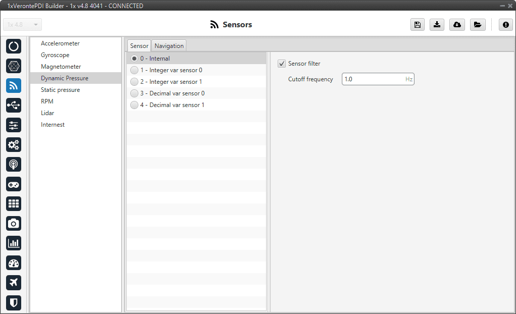
Dynamic Pressure panel - Internal sensor configuration
In this panel it is possible to set different options regarding filters.
Sensor filter: Enables a low pass filter which its cutoff frequency is configured manually, allowing the user to input any desired value in Hz. It is a software filter.
![]()
Integer var sensor 0-1
In this panel it is possible to configure integer variables provided by an external sensor.
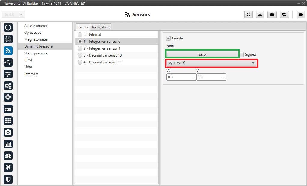
Dynamic Pressure panel - Integer var sensor 0-1 configuration
When Integer var sensor 1 or 2 are selected, the previous panel will be shown. In this panel, the user selects the variable that has been stored in a user variable (Green Box) and the operations that will be carried on (Red Box). It is possible to use the signal through a linear or quadratic relation. The following image shows an example of a linear relation:
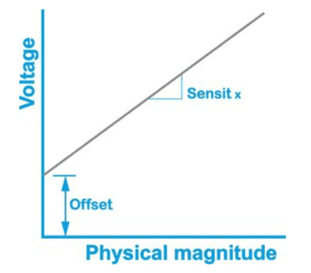
Linear relation of 2 variables
In addition, users must indicate whether the integer value is with sign or without sign. That is, if the “Signed” box is:
Enabled: Integer value with sign.
Disabled: Integer value without sign.
The process of configuration has to be done using custom messages. This is to be configured in the Custom Messages panel of the Input/Output menu. The configuration will depend on the device in use and its communication protocol.
![]()
Decimal var sensor 0-1
In this panel, the user selects a real variable, this does not require a signal treatment. The process of configuration is similar to the one carried out when configuring a Integer Variable.
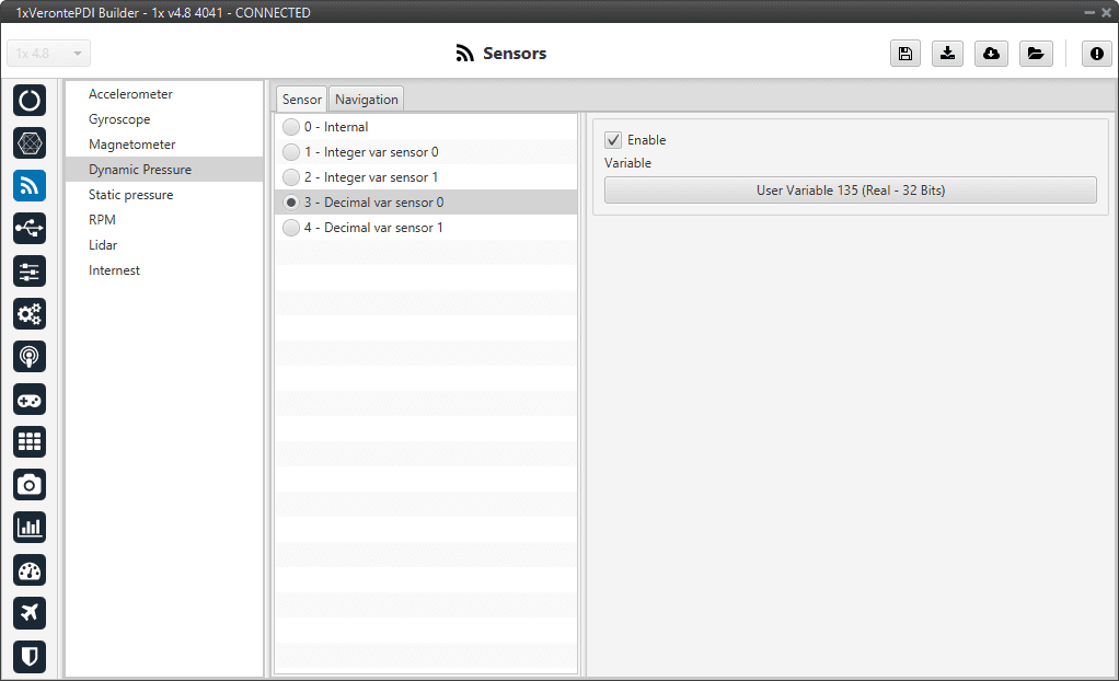
Dynamic Pressure panel - Decimal var sensor 0-1 configuration
Static Pressure
Autopilot 1x has three pressure input lines, two for static pressure to determine the absolute pressure and one for pitot in order to determine the dynamic pressure.
This panel allows the user to configure a static pressure sensor input in 1x.
Important
In this panel, the user can only modify some configurable parameters, the selection of the static pressure sensor and the configuration of the Variance are done in the Static Pressure Sensor - Sensors blocks of the Block Programs menu.
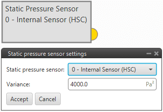
Static Pressure Sensor block
Atmospheric calibration export
The Atmospheric calibration export allows, in a standard ground-air configuration, to continuously send information regarding the static pressure configured on the ground platform to the desired air platform. Therefore, it is a configuration that must be performed on the Veronte Autopilot 1x ground unit.
This function is useful when making long flights as the static pressure varies significantly throughout the day and therefore the altitude estimation will also vary.
Warning
For correct operation both Veronte Autopilots 1x (ground and air units) must measure the same pressure at the same height (this must be checked).
This option is configured independently of the selected Static Pressure sensor.
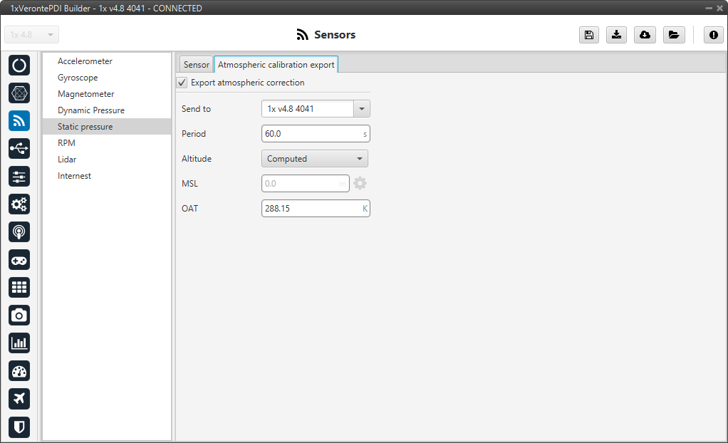
Static Pressure panel - Atmospheric calibration export parameters
Export atmospheric correction: Enables this feature.
This panel has 5 parameters that need to be configured:
Send to: Points to the address where the correction will be sent. For more information on the available addresses, see List of addresses section of the 1x Software Manual.
Period: Period of time spent between sending each correction.
Altitude: There are 2 options available for this parameter:
External: Users can manually enter the altitude if known.
Computed: By selecting this option, the altitude will be computed by the system.
Warning
When this option is selected, it is necessary to add an automation in the 1x ground unit to calibrate the atmosphere periodically (see Atmosphere Calibration action of the Automations menu), to prevent the MSL from drifting.
MSL: Can be entered manually or by a system variable.
Important
This parameter is only enabled when the External option is selected as Altitude.
OAT: Outside Atmospheric Temperature, to be defined by the user.
Sensor
The user can choose between 3 types of source:
Internal Sensor (HSC/MS56/DPS310): Autopilot 1x uses the internal sensor.
Error
If the user has an Autopilot 1x with
hardware version 4.8, although the Internal Sensor HSC is available to be selected in this panel, it is not a sensor of this hardware version.Consequently, selecting it will result in an error in the autopilot configuration.
Integer var sensor 0-1: Autopilot 1x uses a integer value provided by an external sensor.
Decimal var sensor 0-1: Autopilot 1x uses a decimal value provided by an external sensor.
Hint
The following static pressure sensors are suggested:
Internal Sensor MS56
Internal Sensor DPS310
Internal Sensor HSC/MS56/DPS310
This panel displays the possible parameters that can be configured for the internal Static Pressure sensors.
Autopilot 1x has embedded 3 digital static pressure sensors: the DPS310, the MS56 and the HSC. See more information on the pressure ports in Pressure lines - Hardware Installation of the 1x Hardware Manual.
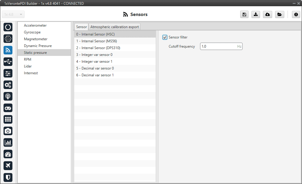
Static Pressure panel - Internal sensors configuration
In this panel it is possible to set different options regarding filters.
Sensor filter: Enables a low pass filter which its cutoff frequency is configured manually, allowing the user to input any desired value in Hz. It is a software filter.
![]()
Integer var sensor 0-1
In this panel it is possible to configure integer variables provided by an external sensor.
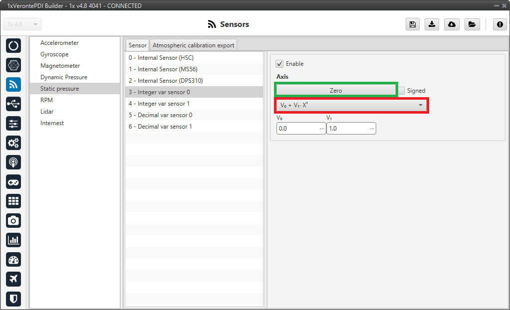
Static Pressure panel - Integer var sensor 0-1 configuration
When Integer var sensor 1 or 2 are selected, the previous panel will be shown. In this panel, the user selects the variable that has been stored in a user variable (Green Box) and the operations that will be carried on (Red Box). It is possible to use the signal through a linear or quadratic relation. The following image shows an example of a linear relation:
Linear relation of 2 variables
In addition, users must indicate whether the integer value is with sign or without sign. That is, if the “Signed” box is:
Enabled: Integer value with sign.
Disabled: Integer value without sign.
The process of configuration has to be done using custom messages. This is to be configured in the Custom Messages panel of the Input/Output menu. The configuration will depend on the device in use and its communication protocol.
![]()
Decimal var sensor 0-1
In this panel, the user selects a real variable, this does not requiere a signal treatment. The process of configuration is similar to the one carried out when configuring a Integer Variable.
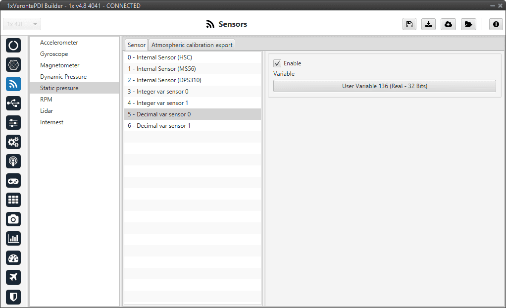
Static Pressure panel - Decimal var sensor 0-1 configuration
RPM
Autopilot 1x can measure RPMs by reading from up to 6 input sources:
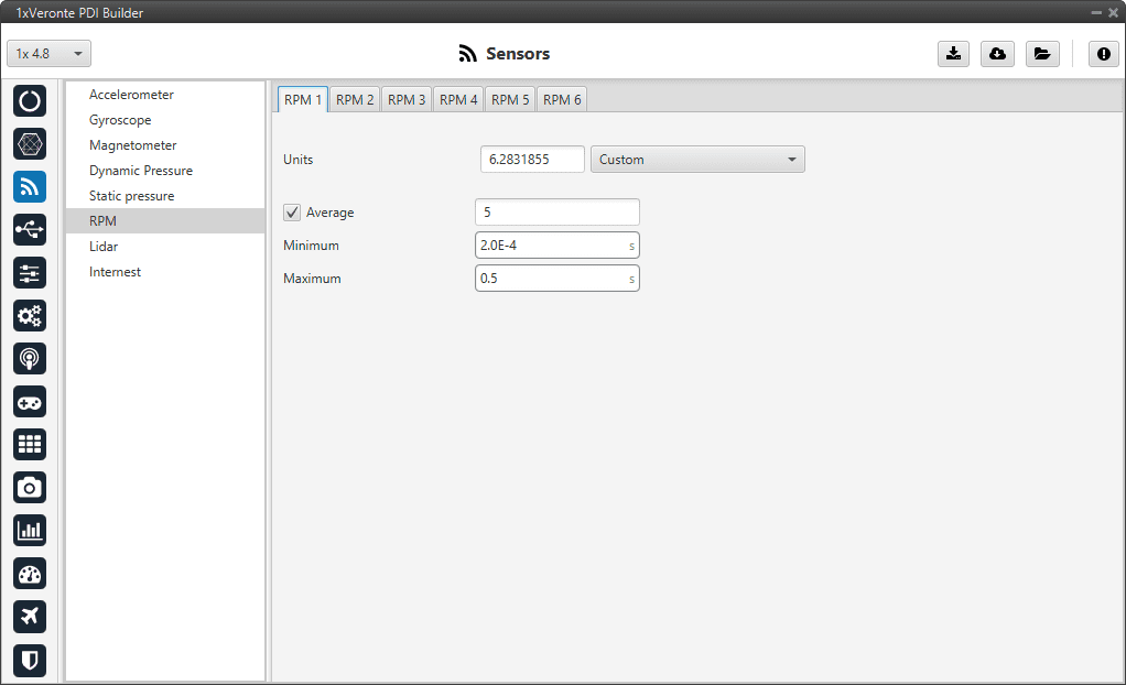
RPM panel
Units: Sensor conversion factor. It can be Custom, Radians per pulse or Pulses per cycle.
Average: Filter to prevent voltage spikes. The readout of the pulse can be filtered as an average output. The amount of measurements to do the average needs to be specified.
Minimum: Here the minimum expected pulse period needs to be specified. This will discard spurius pulses (e.g. induced by EMI) which are smaller than this minimum pulse.
Maximum: This is the maximum period of time allowed without capturing. If no incoming pulse is received for more than this time, the output RPMs will be 0.
Lidar
The I2C bus allows the connection of several devices with different addresses to the same line via master-slave communication. At this moment, Autopilot 1x supports the following Lidar devices:
Garmin Lidar Lite v3: Optical distance measurement sensor with a range of 5 cm to 40 m.
SF11 Lidar: Long range laser altimeter. Supported SF11/B and SF11/C with a range of maximum 50 m and 0.2 m to 120 m respectively.
SF20 Lidar: OEM laser altimeter module. Supported SF20/C with a range of 0.2 m to 100 m.
1x allows up to 5 Lidar devices to be connected to the system at the same time. The configuration panel can be seen below:
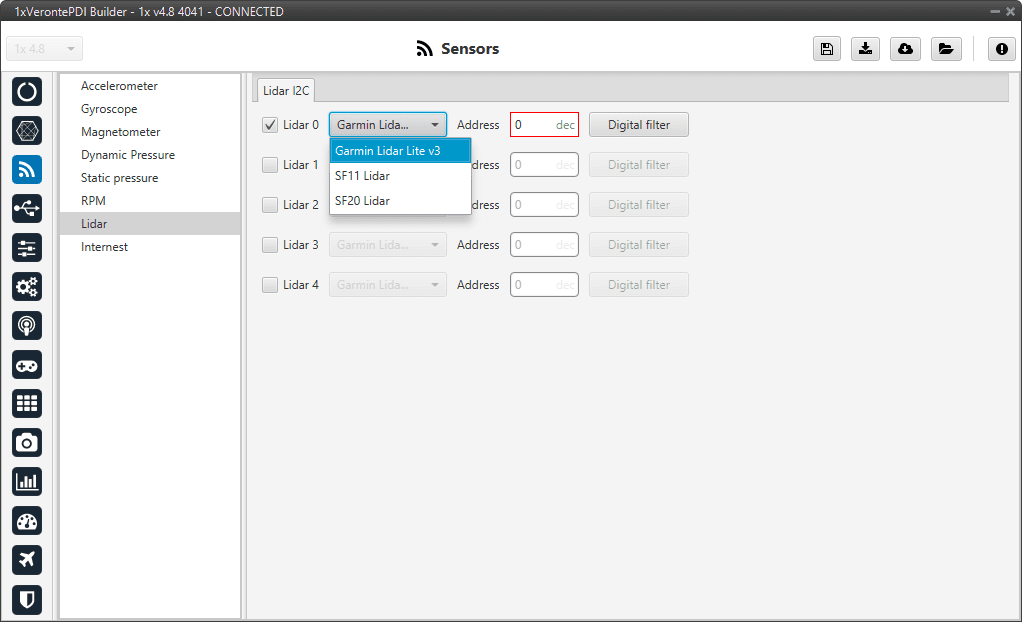
Lidar panel
After enabling the needed number of Lidar devices, configurable parameters are:
Type of Lidar.
Address: With an accepted value between 16 - 239, this is the origin address from the Lidar being configured.
Digital filter: By enabling the Sensor filter checkbox, the user enables a low pass filter which its cutoff frequency is configured manually, allowing the user to input any desired value in Hz. It is a software filter.
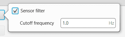
Lidar panel - Digital filter
Warning
I2C address will be different for different devices. Make sure to define it properly by checking the manufacturer documentation.
Note
The Lidar number (Lidar 0/4) needs to be kept in order to properly configure the Altimeter later (this must be done in the Altimeter - Sensors blocks of the Block Programs menu).
Internest
An ultrasound sensor computes Veronte Autopilot 1x position by measuring the time the signal sent out takes to return. The following panel together with Relative position sensor block (see Relative position sensor - Block Programs section) allows the user to configure an Internest system with Veronte Autopilot 1x.
This panel allows the user to choose the version of Internest to be used, its range and the rotation matrix:
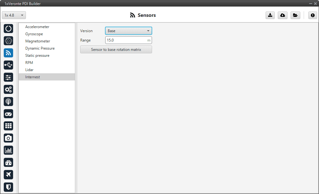
Internest panel
Version: Users must choose the version of the Internest system, the available options are Base and Explore.
Range: Defines the distance at which Internest values will start to be valid.
Sensor to base rotation matrix: Matrix to rotate the system to match the Veronte Autopilot 1x coordinate system.
Internest panel - Rotation matrix